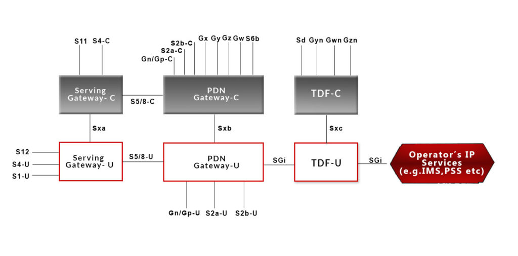
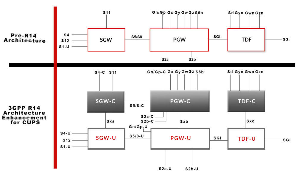
Control Plane and User Plane Separation (CUPS) of the Evolved Packet Core (EPC) materializes scaling of the control plane and user plane independent of one another and promotes a more cost-effective approach to core telecom architecture, the network for 5G.
It provides an adaptable and adjustable network deployment option where operation and independent enhancement of control plane and user plane functionality is possible without affecting the functionality of the existing elements subject to this development.
The requirement of CUPS Architecture
Cellular network, today, is witnessing an increased variation in resource demands across the control and user planes, while earlier requirements were subject to known and calculated elements of control and user plane.
Some devices require high control-plane resources (signaling), while other devices may require very little signaling resources but significant user plane and data resources. With the ever-increasing cellular network requirements, there is an apparent need to further bifurcate and develop the control-plane and user-plane elements individually.
Large Volume Data Support
Cellular operators’ user data traffic has been on the rise, on account of increased use of varied smart devices, the proliferation of video and other applications using cellular networks.
Rich Communication Services
The use of mobile terminals and content-rich multi-media services (e.g. OTT video streaming services, content sharing, Person to person video) growing, this trend of rapidly increasing data traffic is expected to continue and accelerate.
Customer Experience and Low Latency
There is strong consumer demand for user experience improvements, with lower latency being one of the important KPIs to be met on the way.
Control and User Plane Separation (CUPS) Architecture
CUPS architecture for EPC was first introduced in 3GPP release 14. All earlier EPC specification follows NON-CUPS architecture. CUPS introduce 3 new interfaces, Sxa, Sxb and Sxc between the CP and UP functions of the SGW, PGW, and TDF respectively.

- A Control Plane function can interact with multiple User Plane functions, and a User Plane function can be shared by multiple Control Plane functions.
- A UE is served by a single SGW-Control Plane but multiple SGW-User Planes can be selected for different PDN connections. A user plane data packet may roam around multiple User Plane functions.
- The Control Plane function controls the processing of the packets in the User Plane function by provisioning a set of rules in Sx sessions.
- Charging and Usage Monitoring are supported by directing the User Plane function to quantify and report traffic usage, using Usage Reporting Rules. There is hardly any change expected in the charging and policy control functions.
- The Control Plane or User Plane function is responsible for GTPU F-TEID allocation.
- Traditional nodes SGW, PGW, and TDF can be replaced by a split node without affecting connected legacy nodes.

CUPS Architecture Advantages & Efficiency
- Reducing Latency on application service by selecting User plane nodes which are closer to the RAN or more appropriate for the intended UE usage type without increasing the number of control plane nodes. This mechanism is very much efficient for high-bandwidth applications like video. Because the core user-plane node is located near to the end-user, the operator doesn’t have to transmit user data all the way to the central hub and therefore saves money.
- High demand for data traffic supported by adding additional user plane nodes without increasing control plane nodes (SGW-C, PGW-C, and TDF-C) in the network.
- Locating, Scaling and evolution of Control Plane and User Plane resources are done independently
Finally, Control and User Plane Separation (CUPS) facilitates cellular operators to reduce data-center costs by hosting the control plane and the user plane in different geographic locations as well as save transmission costs.


